Please Choose Your Language
- All
- Product Name
- Product Keyword
- Product Model
- Product Summary
- Product Description
- Multi Field Search

Views: 0 Author: Site Editor Publish Time: 2026-07-29 Origin: Site

Machining titanium alloys such as Ti-6Al-4V requires a precise balance between cycle time efficiency and strict surface finish requirements, particularly in high-stakes aerospace and medical manufacturing. Relying on arbitrary stepover percentages leads to excessive scallop heights, tool rubbing, work hardening, and ultimately, costly part rejection or extensive manual rework. Establishing the mathematical and practical relationship between stepover distance, tool diameter, and toolpath strategy is essential for optimizing 3D profiling and achieving predictable surface finishes when using a high-performance titanium ball nose end mill. Operators must move beyond default CAM settings and apply calculated stepover values that account for the unique thermal and mechanical properties of titanium. This approach prevents localized heat buildup and ensures the cutting edge shears the material cleanly rather than smearing it across the workpiece.
Stepover distance directly dictates the scallop (cusp) height left on the workpiece, which mathematically correlates to the theoretical Ra/RMS surface finish.
Titanium’s low thermal conductivity requires highly specific stepover-to-chip-load ratios to prevent localized heat buildup, work hardening, and premature tool degradation.
Avoiding the "dead center" of a titanium ball end mill via tool tilting or inclination is critical to prevent tool rubbing and surface smearing.
Balancing cycle time and surface finish necessitates calculating exact stepover values based on target tolerances rather than relying on default CAM software percentages.
Toolpath strategy (constant scallop vs. raster) and tool engagement angles are as critical to the final finish as the stepover value itself.
In 3D profiling operations, the spherical geometry of a ball nose cutter naturally leaves residual ridges on the material surface as the tool moves laterally between consecutive passes. These ridges are known as scallops or cusps. The stepover is the exact lateral distance the tool shifts after completing one pass. The size of the scallop left behind is directly determined by the tool's radius and the programmed stepover distance. The standard mathematical relationship used by machinists and programmers is: Scallop Height = Tool Radius - √(Tool Radius⊃2; - (Stepover/2)⊃2;). Understanding and applying this formula allows operators to predict the surface texture accurately before the spindle ever turns.
To illustrate how stepover impacts scallop height, consider a standard 0.500-inch diameter ball nose end mill. As the stepover increases, the scallop height grows exponentially, directly affecting the final surface roughness.
| Tool Diameter (inch) | Stepover Distance (inch) | Stepover Percentage | Theoretical Scallop Height (inch) |
|---|---|---|---|
| 0.500 | 0.005 | 1% | 0.000012 |
| 0.500 | 0.010 | 2% | 0.000050 |
| 0.500 | 0.025 | 5% | 0.000313 |
| 0.500 | 0.050 | 10% | 0.001253 |
| 0.500 | 0.100 | 20% | 0.005051 |
Machining 3D slopes and inclined surfaces fundamentally alters the resulting scallop height compared to cutting across flat, planar surfaces. A standard planar stepover stretches out when applied to steep walls, resulting in larger, out-of-tolerance scallops if the toolpath is not dynamically adjusted. When the tool traverses a steep incline, the effective distance between the cutting passes increases along the surface of the part, leaving deeper and wider ridges.
Analyze the maximum slope angle of the part geometry before generating the toolpath.
Select a constant scallop or 3D offset toolpath strategy in the CAM software to maintain uniform ridge heights.
Limit raster or parallel toolpaths to surfaces with less than a 30-degree incline to prevent stepover stretching.
Implement waterline or Z-level finishing for near-vertical walls to ensure the stepdown acts as the effective stepover.
Translating the calculated scallop height into expected Roughness Average (Ra) and Root Mean Square (RMS) values provides a necessary baseline for surface finish expectations. However, theoretical calculations often deviate significantly from actual results when cutting titanium. This discrepancy arises from variables such as tool deflection, machine tool rigidity, spindle runout, and the condition of the tool holder. Titanium's high tensile strength and low modulus of elasticity amplify these variables. If the machining setup lacks absolute rigidity, the tool will push away from the cut, inducing micro-chatter that degrades the surface finish far beyond what the mathematical scallop height predicts.
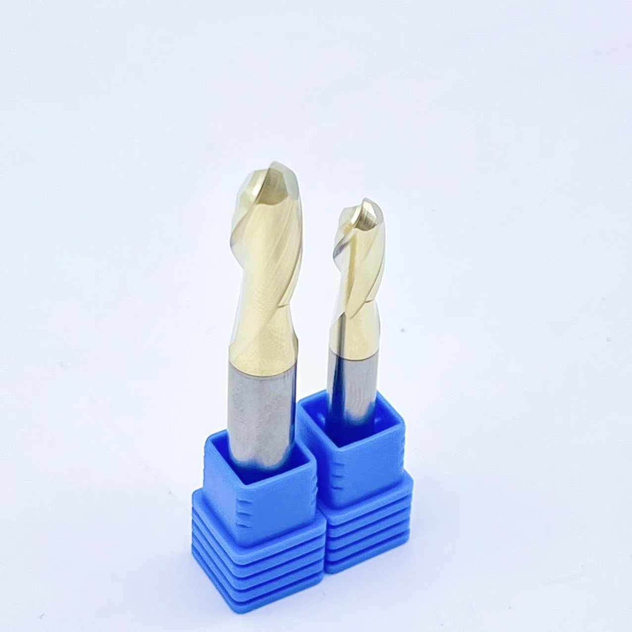
Cutting at the dead center of a titanium ball end mill presents a severe mechanical challenge: the surface footage (SFM) at the very tip of the tool is effectively zero. At this center point, the tool is not shearing the material; it is dragging and rubbing against it. Excessively small stepovers combined with vertical tool orientations cause the tool to rub continuously, inducing rapid work hardening in the titanium alloy and destroying the surface finish. The heat generated by this friction cannot dissipate quickly due to titanium's poor thermal conductivity, leading to catastrophic tool failure.
To solve this, machinists utilize tool inclination. By tilting the tool spindle or the workpiece by 10 to 15 degrees using 4-axis or 5-axis machine configurations, the cutting action shifts away from the dead center tip. This inclination engages the flutes where the surface speed is sufficient for efficient shearing, ensuring a clean cut, reducing localized heat buildup, and producing superior surface finishes.
There is a strict inverse relationship between cycle time efficiency and surface finish quality. Larger stepovers increase the Material Removal Rate (MRR) and reduce cycle times, but they leave prominent scallops that require secondary finishing operations. Conversely, smaller stepovers produce excellent surface finishes but drastically increase the time the tool spends in the cut. Evaluating the cost of extended CNC machine time versus the cost and dimensional risks of manual polishing is a daily requirement in aerospace and medical manufacturing. In titanium machining, aggressive stepovers during the roughing phase must be carefully balanced with precise micro-stepovers during the finishing phase to maintain part integrity without inflating production costs.
The number of flutes on a cutting tool directly impacts the allowable feed rates and the effective stepover limits without overloading the cutter. More flutes allow for higher feed rates at a given chip load, but they also reduce the available chip clearance space in the gullets. When navigating complex 5-axis geometries and variable surface slopes, selecting an aerospace contour end mill with optimized flute geometry is essential. The tool must maintain consistent chip evacuation to prevent chip packing and subsequent tool deflection during aggressive stepovers. Variable pitch and variable helix designs help break up harmonics, reducing chatter when the tool is engaged in heavy stepover cuts.
A coated ball nose end mill utilizing AlTiN, TiAlN, or specialized silicon-based nanocomposite coatings is required to withstand the extreme heat generated by aggressive stepover parameters in titanium. These high-performance coatings reduce friction at the cutting edge and act as a thermal barrier, directing heat into the chip rather than the tool substrate. Coating wear patterns emerge based on the stepover direction, radial engagement, and prolonged time-in-cut. Maintaining the integrity of the coating is critical for holding a consistent surface finish over large titanium components, as a degraded coating will immediately lead to material smearing and poor Ra values.
Different stages of the machining process require distinct stepover strategies to optimize both tool life and part quality. For roughing operations, high stepovers ranging from 20% to 40% of the tool diameter prioritize MRR and bulk material removal. The goal here is to clear material quickly without regard for the resulting scallop height. Semi-finishing requires an intermediate stepover, typically 5% to 10% of the tool diameter, to remove the large roughing scallops and leave a uniform, thin layer of stock for the final pass. Finishing demands micro-stepover calculations, usually 1% to 5% of the tool diameter, to meet the stringent Ra requirements of critical components like a medical implant ball nose cutter.
Modern CAM software allows programmers to input a target scallop height directly rather than relying on a static stepover percentage. This scallop-first workflow ensures that the software automatically adjusts the stepover distance based on the tool diameter and the surface slope. Comparing Raster, Waterline, and Scallop (Constant Stepover) toolpaths highlights how surface slope angle affects scallop distance in planar toolpaths. Dynamic stepover adjustments in CAM software maintain consistent scallop heights across steep walls and shallow floors, ensuring a uniform finish regardless of the part's topography.
Long tool overhangs and high cutting forces in titanium cause chatter and micro-deflections, ruining the surface finish regardless of correct stepover math. When a tool deflects, it fails to cut exactly where programmed, leading to uneven scallop heights and a degraded surface texture. To mitigate this risk, operators must mandate the use of rigid workholding, shrink-fit or hydraulic tool holders, and the shortest possible stub-length tools. Absolute rigidity is non-negotiable when executing fine stepover finishing passes in tough titanium alloys.
Re-cutting hardened titanium chips in tight, overlapping stepover passes leads to surface tearing, smearing, and chipped cutting edges. Because titanium chips work-harden immediately upon being sheared, dragging them back through the cutting zone destroys the surface finish. Implementing high-pressure, through-spindle coolant or precise flood coolant strategies tailored specifically for 3D profiling is necessary to evacuate chips immediately. Proper coolant application prevents chip recutting, provides necessary lubricity, and manages the intense heat generated at the cutting zone.
Optimizing stepover for titanium machining requires a calculated approach that balances tool geometry, material properties, and surface finish requirements.
Calculate the maximum allowable scallop height based on the specific part tolerance and Ra requirements before programming the toolpath.
Select the largest practical tool diameter for the geometry to minimize the number of passes and reduce overall cycle time.
Utilize tool inclination strategies in your CAM software to avoid center-tip rubbing and prevent work hardening of the titanium surface.
Implement constant-scallop or 3D offset toolpaths to maintain uniform surface finishes across varying slopes and complex geometries.
A: For finishing titanium, a starting stepover of 1% to 5% of the tool diameter is standard. This micro-stepover minimizes scallop height and helps achieve strict Ra requirements, though the exact value must be calculated based on the specific surface finish tolerance and the tool diameter being used.
A: Scallop height is calculated using the formula: Scallop Height = Tool Radius - √(Tool Radius⊃2; - (Stepover/2)⊃2;). Modern CAM software typically calculates this automatically when you input a target surface finish or maximum cusp height.
A: Smeared or torn finishes often result from cutting at the dead center of the ball nose, where surface speed is zero. This causes the tool to rub rather than shear, leading to rapid work hardening and poor surface quality in titanium.
A: Yes. A larger tool diameter creates a shallower scallop for a given stepover distance. Using the largest practical tool diameter allows for a larger stepover while maintaining the exact same surface finish, thereby reducing cycle time.
A: Tilting the tool 10 to 15 degrees moves the cutting action away from the zero-speed tip to the outer flutes, where proper shearing occurs. This prevents rubbing, reduces heat generation, and significantly improves the final surface finish.
A: Smaller stepovers drastically increase cycle time because the tool must make significantly more passes to cover the same surface area. Balancing the required surface finish with acceptable cycle times is critical for efficient production.


