Please Choose Your Language
- All
- Product Name
- Product Keyword
- Product Model
- Product Summary
- Product Description
- Multi Field Search

Views: 0 Author: Site Editor Publish Time: 2026-09-20 Origin: Site

Every machinist knows the sound. That sudden, high-pitched squeal from the spindle usually means an insert is about to shatter. Grooving is an inherently hostile operation. When metal ribbons jam or a blade deflects inside a confined cavity, the resulting failure destroys the cutter and often scraps a high-value workpiece. Standard off-the-shelf tooling might survive basic applications in mild steel. However, these generic options frequently buckle when confronted with complex geometries, tight tolerances, or tough aerospace alloys.
Operators on the shop floor require engineered reliability. Optimizing three critical variables—width, depth, and chip control—is the absolute secret to eliminating unplanned downtime and maximizing metal removal rates. This technical breakdown explains exactly how to evaluate and deploy the right equipment to conquer demanding grooving challenges.
Precision is Non-Negotiable: Holding exact groove widths requires rigid clamping mechanisms and tight indexing tolerances to prevent microscopic dimensional deviations.
Depth Dictates Tool Rigidity: Deeper cuts exponentially increase the risk of chatter. Upgrading substrate materials to micro-grain carbide is a mandatory step for maintaining structural integrity.
Chip Control is the Primary Bottleneck: Without engineered chip breakers and high-pressure coolant, chips pack tightly into the groove, causing rapid heat accumulation and catastrophic tool failure.
Application-Specific Selection: Choosing the correct cutter architecture depends entirely on the machine kinematics, specifically whether you are turning on a lathe or interpolating on a mill.
Grooving is fundamentally distinct from standard turning or face milling. In a typical pass, the cutting edge is walled in by the workpiece material on three sides. This highly restrictive environment generates immense friction, suffocates heat dissipation, and severely complicates chip evacuation.
General-purpose cutting tools are built for versatility rather than specialized performance. When pushed into high-volume or high-precision tasks, their limitations surface immediately. They often lack the sheer edge sharpness required to slice material cleanly within a confined space. Consequently, machinists battle accelerated wear, heavily scored surface finishes on the groove walls, and inconsistent dimensional accuracy.
Looking at the broader manufacturing landscape, recent industry data highlights a definitive shift in machining strategies. As the aerospace, electric vehicle, and energy sectors increasingly rely on heat-resistant superalloys and miniaturized components, the demand for highly specialized grooving solutions has surged. Facilities are actively moving away from one-size-fits-all setups. Instead, manufacturing engineers are investing in custom-engineered geometries tailored for specific profiles like complex O-ring grooves or retaining ring slots. These bespoke tools often combine multiple operations, such as simultaneous grooving and chamfering. This integration drastically slashes cycle times, reduces scrap rates, and delivers a highly measurable return on investment.
Achieving and holding accurate widths is a daily battle in precision manufacturing. For hydraulic seals and aerospace fasteners, a deviation of a few tenths of a thousandth of an inch can cause a catastrophic leak.
The dimensional accuracy of the final feature is directly inherited from the cutting insert. High-performance precision machining tools are manufactured with aggressive dimensional tolerances. Premium industrial lines often grind these inserts to within plus or minus 0.002 millimeters. Beyond basic dimensions, edge preparation dictates tool survival. A meticulously honed edge or a specialized T-land design fortifies the cutting boundary. This specific geometry prevents the micro-chipping that gradually alters the effective cutting width over a long production run. Consistent edge preparation ensures the thousandth part measures exactly like the first.
Machinists must strategically choose their toolpath based on the target width and the rigidity of their CNC equipment. Single-cut grooving is highly efficient for standard dimensions where the insert perfectly matches the required width. Because the entire cutting edge engages the material simultaneously, it generates massive radial cutting forces. This approach demands exceptional machine rigidity. Alternatively, when the blueprint calls for a groove wider than the available insert, a multiple-pass strategy is required. The tool plunges, retracts, and steps over repeatedly. Overlapping passes must be calculated flawlessly to maintain perfectly perpendicular walls and prevent uneven ridges on the groove floor.
Deep grooving is brutal on equipment. The fundamental physics are unavoidable. The deeper the required cut, the longer the tool overhang must be. This increased extension exponentially compromises the structural rigidity of the assembly, opening the door to deflection, severe chatter, and unacceptable surface finishes.
Tool overhang length directly dictates rigidity. We measure this using the length-to-diameter ratio. As this ratio climbs, the tool becomes highly susceptible to bending forces. Deflection pushes the tool off its centerline, causing the insert to rub rather than shear the metal. This rubbing spikes the heat zone and accelerates wear. To combat this, engineers must specify tool holders with the absolute largest cross-section that can physically clear the groove walls.
When pushing past a length-to-diameter ratio of 3 to 1, steel tool holders typically vibrate uncontrollably. Transitioning to a solid carbide milling cutter or a carbide-reinforced blade becomes essential. Tungsten carbide boasts a stiffness approximately three times higher than steel. This massive structural integrity resists deflection under heavy radial loads, dampens harmonic vibrations, and allows operators to program deeper cuts without sacrificing dimensional control.
Furthermore, face grooving introduces a unique geometric nightmare because the groove is curved. The tool must plunge axially into the face of a spinning part. If a straight blade is used, the heel of the tool will inevitably crash into the inner or outer diameter of the curved wall. Specialized face grooving blades are engineered with specific axial clearances and curvatures. Matching the exact blade curvature to the target diameter range is mandatory to prevent a violent machine crash.
Because the cutter is boxed in, chips cannot flow freely away from the shear zone. If ignored, continuous ribbons of metal will pack tightly into the cavity. Once jammed, they act as a destructive abrasive, scoring the workpiece walls and ultimately snapping the tool.
Effective evacuation relies entirely on manipulating chip formation. Premium grooving tools feature intricate three-dimensional topographies molded directly into the rake face. A correctly specified chip breaker forces the continuous metal chip to fold, narrow in width, and curl into tight shapes. This narrowing ensures the chip does not scratch the sidewalls as it exits. Once curled tightly enough against the workpiece, the chip fractures and flushes away safely.
While chip breakers handle the mechanical folding, coolant provides the brute force required for ejection. Traditional flood coolant is often useless here because it vaporizes into steam before ever reaching the cutting edge at the bottom of a deep groove. Through-tool high-pressure coolant is the definitive solution. Tools equipped with targeted nozzles blast fluid directly at the insert interface, often exceeding 1000 PSI. This high-velocity stream violently ejects chips while simultaneously quenching the heat zone, which drastically extends insert life.
Navigating the tooling landscape requires a clear understanding of machine kinematics. The terminology can overlap, but selecting the right architecture depends entirely on whether you are standing in front of a lathe or a CNC mill.
Tool Architecture | Machine Platform | Kinematic Action | Best Application | Chip Evacuation Risk |
|---|---|---|---|---|
Indexable Groove Cutter | CNC Lathe / Turning Center | Tool is stationary, workpiece rotates | Outer diameter, inner diameter, and face grooves on cylindrical shafts. | High risk in deep cavities; requires high-pressure coolant. |
Slot Cutter | CNC Milling Machine | Tool rotates, workpiece is stationary | Linear channels, T-slots, and keyways on flat prismatic surfaces. | Medium risk; staggered tooth designs help break up forces. |
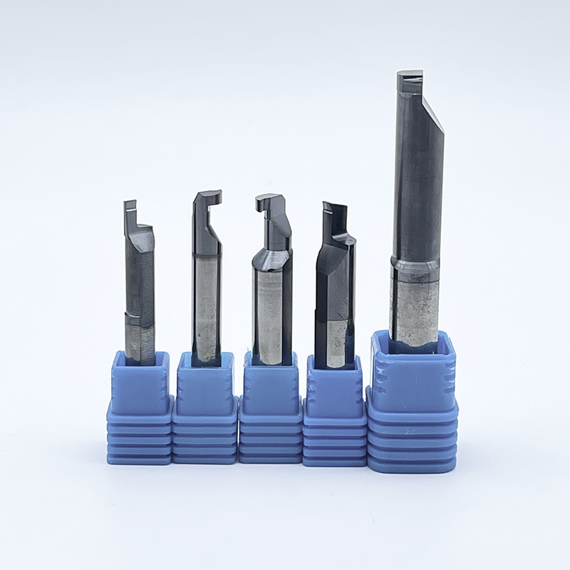
Solid Carbide Thread/Groove Mill | CNC Milling Machine | Helical interpolation inside a bore | O-ring grooves in asymmetrical parts or off-center holes. | Low risk; tool diameter is smaller than the groove, allowing chips to escape. |
On turning centers, the indexable groove cutter is the undisputed industry standard. Utilizing a replaceable carbide insert locked into a robust holder, these tools are highly efficient for machining symmetrical features on flanges. Moving from the lathe to the mill changes the dynamic entirely. A slot cutter is specifically deployed for milling applications. Encompassing variations like Woodruff keyseat cutters, they feature multiple cutting teeth around their periphery to machine straight slots. For large or unbalanced parts that cannot be rotated on a lathe, engineers utilize solid carbide milling tools via circular interpolation. This method is incredibly advantageous for machining internal grooves because the tool leaves ample room for chips to escape.
For technical buyers evaluating cost-per-part, tool geometry is only half the equation. The metallurgical composition and surface treatment of the cutter dictate its thermal stability and ultimate lifespan, especially when machining abrasive or gummy materials.
The core of any high-performance cutter is its substrate. Micro-grain tungsten carbide is the industry standard due to its exceptional balance of hardness and toughness. For interrupted cuts or older machines lacking rigidity, a tougher carbide grade with higher cobalt content absorbs shock and prevents edge chipping. In contrast, for continuous grooving in highly abrasive materials, a harder substrate with less cobalt provides superior wear resistance.
Because grooving traps heat, operating uncoated carbide is a recipe for built-up edge, where workpiece material pressure-welds to the insert. Advanced coatings applied via Physical Vapor Deposition or Chemical Vapor Deposition are mandatory. Titanium Aluminum Nitride is a coating essential for machining abrasive cast irons and high-temperature alloys. Under intense heat, the aluminum oxidizes to form a microscopic shield, protecting the carbide from thermal shock. Alternatively, Titanium Carbonitride is extremely hard with a low coefficient of friction, making it perfect for sticky materials like low-carbon steel and aluminum.
Sifting through massive tooling catalogs requires a systematic approach. Implementing a structured evaluation framework prevents costly trial-and-error on the shop floor.
Start by objectively evaluating your CNC machine's physical limitations. Wide plunge cuts demand significant spindle torque. If the machine lacks structural rigidity, a single wide plunge will generate violent chatter, necessitating a narrower tool and a multiple-pass strategy. Verify your coolant capabilities. If your machine supports high-pressure coolant, prioritizing through-coolant tooling will yield massive productivity gains.
The physical properties of the metal dictate the tool grade and edge preparation. Machining hardened steels requires heavily honed edges and heat-resistant coatings. Cutting soft aluminum demands razor-sharp, polished edges to prevent material adhesion. Batch size also matters. High-volume runs justify the cost of premium custom tools, whereas low-volume prototyping might favor versatile general-purpose cutters.
Standard geometries fall short when blueprints call for multi-radii grooves, tight undercuts, or complex chamfers. Manufacturing engineers should collaborate directly with tooling manufacturers. By sharing CAD models and operational constraints, tooling experts can engineer application-specific holders and inserts that maximize metal removal rates and drive down your cost per part.
Mastering groove widths and conquering deep cavity cuts requires exceptionally rigid tooling and a deep understanding of machining kinematics. Flawless chip control, driven by engineered breakers and high-pressure coolant, is the ultimate barrier against tool failure and machine downtime.
While standard tools may suffice for the simplest jobs, upgrading to specialized cutters drastically lowers your overall cost per machined part. By matching the right micro-grain substrate, coating, and tool architecture to your exact machine setup, you ensure consistent tolerances and increased daily output. Stop letting scrap rates eat into your profit margins. Whether you need custom geometries for aerospace alloys or high-volume production cutters, explore the high-performance cutting solutions at SSENDMILL to find the exact engineered match for your next project.
These terms refer to tools utilized on entirely different machine platforms. A groove cutter is typically an indexable, stationary tool used on a CNC lathe for turning circular profiles, such as outer diameter, inner diameter, and face grooves. Conversely, a slot cutter is a rotary multi-tooth tool deployed on a milling machine. Slot cutters traverse across a stationary workpiece to mill straight channels, keyways, or T-slots into flat surfaces.
Chip evacuation is the primary cause of catastrophic failure in deep grooving. To prevent jamming, utilize inserts equipped with aggressive, engineered chip breakers designed to fold and fracture chips into tight shapes. Implement high-pressure through-tool coolant to physically blast the chips out of the cavity. Programming a peck grooving cycle, where the tool briefly retracts to break the chip mechanically, is also a highly effective strategy for deep radial cuts.
Feed rate directly dictates chip thickness, which is critical for engaging the chip breaker. If the feed is too light, chips become stringy and wrap around the tool. If it is too heavy, the radial pressure will deflect the blade or stall the spindle. A standard baseline is to start at 0.10 millimeters per revolution for steel. However, in deep grooving, you should reduce the feed rate by 20 to 30 percent as the tool reaches the bottom of the cavity to compensate for reduced coolant flow and increased friction.
Aluminum is notoriously gummy and prone to built-up edge, where the metal welds itself to the cutting tool. Avoid coatings containing aluminum, such as Titanium Aluminum Nitride, because they have a chemical affinity with the workpiece. Instead, use an uncoated, highly polished micro-grain carbide insert, or opt for a Titanium Carbonitride or Zirconium Nitride coating. These provide a very low coefficient of friction, allowing the chips to slide out of the groove smoothly without sticking to the rake face.
A solid carbide milling cutter is strongly recommended when the workpiece is too large, heavy, or unbalanced to be safely rotated on a lathe spindle. Furthermore, milling cutters are essential when machining internal grooves inside off-center holes on a stationary part. By utilizing a CNC programming technique called circular interpolation, the rotating milling cutter can precisely machine the circular cavity while leaving ample space for chips to evacuate.
Yes, many tool manufacturers design hybrid inserts capable of both parting and standard grooving. However, there are distinct trade-offs to consider. Dedicated grooving inserts typically feature a perfectly flat cutting edge designed to leave a precise, smooth finish at the bottom of the groove. Parting tools often feature an angled lead edge, such as 5 to 15 degrees, to minimize the burr left on the center of the workpiece as it falls away. Using an angled parting tool for a standard groove will result in a slanted, out-of-tolerance floor.