Please Choose Your Language
- All
- Product Name
- Product Keyword
- Product Model
- Product Summary
- Product Description
- Multi Field Search

Views: 0 Author: Site Editor Publish Time: 2026-09-20 Origin: Site

Every machinist knows the dreaded sound. A high-pitched squeal echoes through the shop, immediately followed by the sharp crack of a snapped neck inside a blind channel. Machining T-slots is notoriously unforgiving. It frequently results in broken tools and heavily scrapped parts. Standard catalog cutters simply fail to hold the tight tolerances required for complex workholding setups.
Specialized tooling solves this dilemma. By optimizing chip flow and reinforcing structural weak points, custom geometry keeps the process stable. In this technical breakdown, we will uncover exactly how cutter design ensures flawless groove accuracy and prevents catastrophic failures on the machine table.
Geometry Controls Accuracy: The rake angle, clearance angle, and flute design dictate chip flow and prevent tool deflection.
Material Synergies: Pairing optimal geometry with solid carbide substrates drastically reduces wear and maintains dimensional stability over long production runs.
Customization Yields ROI: Off-the-shelf tools suit general work, but custom tooling offers the highest return on investment for strict tolerance requirements.
Process Optimization is Mandatory: Even the most advanced cutter requires a strict multi-step milling strategy to prevent sudden tool failure.
T-slots are foundational elements in manufacturing. You will commonly find them on machine tool tables, workholding jigs, and structural aluminum framing. Their primary function allows T-nuts to slide smoothly along a track while providing immense clamping force when tightened. Creating this internal undercut presents significant engineering hurdles that standard tooling cannot overcome.
The fundamental issue with undercutting is the physical confinement of the cutting zone. Once a cutter enters the undercut area, it operates in a blind channel. This creates a severe bottleneck for chip evacuation.
When standard end mills are modified or forced into this application, they typically lack adequate chip gullet space. Consequently, chips become permanently trapped inside the groove. This entrapment leads to recutting, where the cutting edges grind against previously sheared metal chips. Recutting exponentially increases heat generation and degrades the surface finish of the slot walls. More importantly, it places immense torsional stress on the tool neck, ultimately resulting in sudden tool breakage. Effective slot machining in these confined spaces requires highly specialized geometry to forcefully eject chips out of the cutting zone.
Accuracy in a T-slot is absolutely non-negotiable. The dimensions of the groove dictate how well the mating T-nut will function. We specifically look at width, depth, and the parallelism of the walls. If the groove is too tight, the nut binds. If it is too loose, the clamping mechanism suffers from play. This looseness leads to vibration and inaccuracy during subsequent machining operations. Achieving this exactness requires precision milling techniques that eliminate tool deflection and maintain constant cutting pressure. These variables depend heavily on the cutter design.
Looking at the current manufacturing landscape, we see a distinct shift in machining philosophies. High-mix, low-volume production environments are aggressively phasing out older tooling strategies. This is especially true within the aerospace and electric vehicle sectors. Modern 5-axis CNC centers are capable of immense spindle speeds. Therefore, the bottleneck is no longer the machine, but the cutter itself.
Shops are increasingly adopting dry machining or minimum quantity lubrication to reduce environmental impact and coolant costs. This evolution makes traditional materials obsolete for undercutting. It cements the necessity for highly engineered substrates that can withstand extreme thermal shock while maintaining micron-level precision.
A standard catalog end mill is designed for versatility. It is capable of profiling, slotting, and plunging across various applications. Specialized tooling is engineered for a singular, highly specific task. In the context of T-slots, a standard tool is elevated to specialized status through custom dimensional ratios and specific carbide substrates. We also apply targeted physical geometries addressing the undercut environment.
For engineering teams looking to eliminate scrap and reduce cycle times, investing in purpose-built tooling is a calculated decision. It is based on blueprint tolerances rather than initial procurement costs.
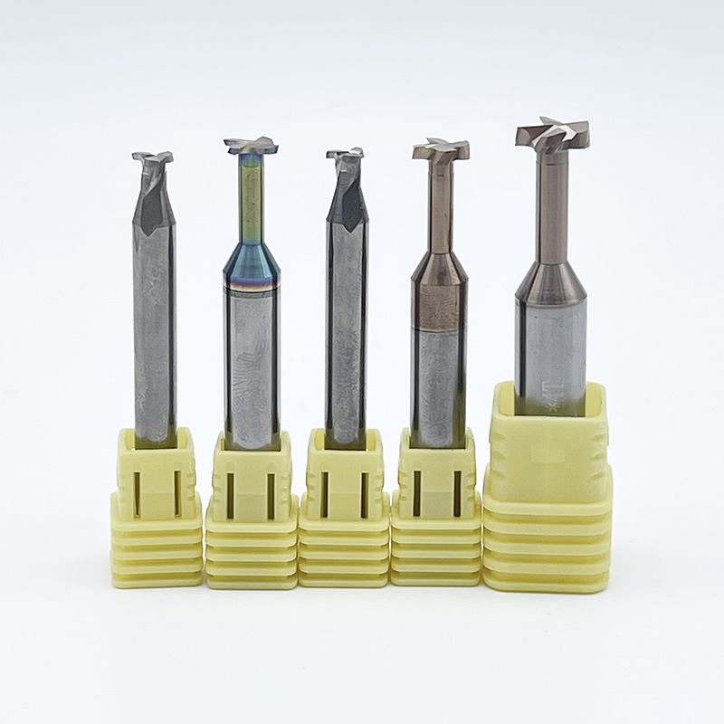
To understand why these tools are unique, one must examine their physical anatomy. A T-slot end mill consists of four primary sections.
The Cutting Head: Determines the final width of the undercut.
The Neck Diameter: Must be narrower than the vertical access slot to prevent rubbing against the walls.
The Neck Length: Dictates how deep into the workpiece the undercut can be machined.
The Shank: The upper portion held securely by the machine tool holder, often requiring an h6 tolerance for maximum concentricity.
The critical vulnerability lies in the ratio between the cutting head and the neck diameter. Because the neck must be thinner than the head to clear the vertical slot, the tool is inherently fragile. A thick neck provides rigidity but limits the size of the vertical slot. A thin neck allows for a smaller access slot but increases the risk of deflection and snapping. Specialized engineering calculates the exact mathematical balance required to maintain rigidity while allowing sufficient clearance.
A standard end mill cuts on its periphery and its bottom. However, a dedicated groove milling cutter designed for T-slots must cut on its periphery, its bottom, and its top inner edges simultaneously. Standard tools lack the top cutting edges required to form the upper lip of the undercut. They also do not possess the necessary neck relief to operate inside a previously roughed channel without causing catastrophic friction.
The secret to holding strict tolerances lies in the physics of the cutting action. Every angle and curve ground into the tool dictates how it interacts with the workpiece material.
The number of cutting edges is a primary factor determining both surface finish and chip evacuation capability. Selecting the correct flute count is a strict trade-off between the space available for chips to escape and the structural rigidity of the core web.
Low Flute Count: Tools with 2 to 3 flutes feature deeper chip gullets. These are highly recommended for non-ferrous materials like aluminum or plastics, which produce large, stringy chips. The extra space prevents the chips from packing and snapping the tool.
High Flute Count: Tools with 4 to 6 flutes maintain a thicker core web, providing maximum rigidity. They are essential for machining harder materials like cast iron, carbon steel, and titanium. Harder materials tend to produce smaller, fractured chips that are easier to flush out of smaller gullets.
Workpiece Material | Recommended Flute Count | Primary Benefit | Risk of Incorrect Selection |
|---|---|---|---|
Aluminum Alloys | 2 - 3 | Maximum chip evacuation | Chip packing and tool breakage |
Mild Steels | 3 - 4 | Balance of finish and clearance | Poor surface finish |
Cast Iron | 4 - 6 | High rigidity, reduced chatter | Tool deflection, oversized groove |
Titanium / Inconel | 4 - 6 | Heat distribution, tool life | Rapid edge wear, thermal failure |
The rake angle is the angle of the cutting face relative to the workpiece. It determines the shearing action of the tool. A positive rake angle creates a sharper edge that slices through the material with minimal resistance. Reducing cutting force is critical because it minimizes the lateral pressure pushed against the weak neck of the cutter.
By lowering cutting resistance, a positive rake angle significantly decreases tool deflection. Deflection is the leading cause of inaccurate groove widths. If the tool bends away from the material during the cut, the resulting slot will be tapered or completely out of tolerance.
The helix angle refers to the spiral of the flutes along the cutting head. A standard helix provides a consistent cutting force. Yet, in the confined space of a T-slot, harmonic vibrations quickly build up. This results in chatter. Chatter leaves a wavy, unacceptable surface finish on the groove walls and accelerates tool wear.
Advanced cutters utilize staggered or variable helix designs, alternating between 35 and 38 degrees. This variable geometry breaks up the harmonic frequencies generated during the cut. It ensures the tool remains stable and the groove walls remain perfectly parallel and smooth.
The corners of a cutting tool are its most vulnerable points. When a sharp 90-degree corner engages the workpiece, it absorbs massive amounts of stress and heat. This leads to premature chipping. By integrating a slight corner radius or a chamfer into the tool geometry, manufacturers distribute the cutting forces over a larger surface area.
This modification protects the tool from chipping while leaving a small internal radius inside the machined part. Eliminating sharp internal corners removes stress concentrators, thereby increasing the overall structural integrity of the finished component.
Historically, High-Speed Steel was used for custom tooling due to its lower cost and ease of grinding. Today, modern manufacturing tolerances demand the superior physical properties of special carbide tools.
The primary metric of importance here is stiffness. A 0.6-micron solid tungsten carbide substrate is nearly three times stiffer than High-Speed Steel. In the context of a T-slot cutter, this stiffness is paramount. A carbide tool resists bending under lateral cutting forces far better than a steel counterpart. It ensures the cutter remains perfectly perpendicular to the workpiece. While carbide is more brittle and requires highly rigid machine setups, its ability to hold dimensional stability makes it the undisputed industry standard.
In confined slot milling, heat is the ultimate enemy. Without proper evacuation, the ambient temperature inside the groove causes chips to weld directly to the cutting edge. This failure mode is known as Built-Up Edge. It alters the tool geometry, causing it to tear the material rather than cut it cleanly. This instantly ruins the groove accuracy.
Advanced physical vapor deposition coatings act as thermal and lubricious barriers. Coatings such as Titanium Aluminum Nitride or Aluminum Titanium Nitride excel in these harsh environments. When exposed to high cutting temperatures, the aluminum in these coatings forms a microscopic layer of aluminum oxide. This layer reflects heat into the chip rather than allowing it to absorb into the tool core. The low coefficient of friction provided by the coating allows chips to slide smoothly out of the flutes.
Machining a T-slot is fundamentally different from standard profiling or face milling operations. The tool operates in a highly confined, semi-blind space. Implementing a strict, standardized process is mandatory to maintain groove accuracy and prevent tool failure.
One of the most common errors on the shop floor is attempting to machine a T-slot in a single operation. The unique geometry of these cutters makes them highly susceptible to torsional shear stress. Plunging this tool directly into solid material places an overwhelming load on the weakest point of the cutter.
To achieve reliable results, machinists must employ a rigorous two-step methodology.
Step 1: The Roughing Pass. Before the specialized cutter ever touches the workpiece, you must rough out the central vertical channel using a standard solid carbide end mill. The width of this roughing channel should be slightly wider than the neck diameter of your T-slot tool, but strictly narrower than the final upper slot dimension. This critical step removes the bulk of the material, creating a necessary void that serves as an evacuation path for chips.
Step 2: The Undercutting Pass. Only after the central channel is cleared should you introduce the T-slot tool to machine the horizontal undercut. Because the vertical channel is already empty, the specialized cutter only engages material on its outer periphery. This drastically reduces the radial cutting forces applied to the fragile neck, minimizing tool deflection.
Even with optimal cutter geometry, incorrect running parameters will induce harmonic chatter.
Surface Footage: T-slot cutters generally require lower surface speeds compared to standard end mills. The rotational velocity must be conservative to manage the heat generated in the confined undercut.
Chip Load: The feed rate per tooth must be carefully calibrated. If the feed is too low, the cutting edge will rub rather than shear, causing rapid work hardening. If the feed is too high, the resulting radial forces will deflect the tool head.
Coolant Strategy: Standard flood coolant often lacks the velocity to flush heavy chips out of the undercut. High-pressure through-coolant or a targeted, high-velocity air blast is far superior. For carbide tools, an air blast is often preferred as it forcefully ejects chips while eliminating the risk of thermal shock.
Groove accuracy is heavily dependent on the rigidity of the entire machining assembly. Total Indicator Runout affects T-slot cutters more severely than standard tools due to the lever-arm effect of the extended neck. If a four-flute cutter experiences just 0.002 inches of runout, a single flute bears the entire chip load. This leads to immediate micro-fractures on the cutting edge. Utilizing high-precision shrink-fit chucks or hydraulic tool holders with an h6 shank tolerance is highly recommended.
Selecting the correct tool requires matching the cutter specific geometric attributes to the physical properties of the workpiece material.
Different materials exhibit distinct shearing behaviors. They necessitate specific geometric configurations to maintain tight tolerances.
Aluminum and Non-Ferrous Metals: These materials are relatively soft but highly gummy. They require a cutter with a high positive rake angle, typically 15 to 20 degrees, to shear the material cleanly. Polished flutes and a lower flute count are essential to prevent sticky aluminum chips from packing into the flutes.
Carbon Steels and Cast Iron: Ferrous materials demand high structural rigidity. Tools designed for these metals feature lower rake angles, around 5 to 10 degrees, to reinforce the cutting edge against heavy impact forces. A higher flute count distributes the cutting forces evenly across the tool.
Titanium and Superalloys: Machining these aerospace-grade materials generates immense localized heat. Tools must feature variable helix angles to disrupt harmonic chatter frequencies and require advanced coatings to withstand extreme thermal degradation.
Standard off-the-shelf tools are manufactured to nominal dimensions and suit general-purpose fixturing. However, many engineering blueprints require strict tolerances, like plus 0.0005 to minus 0.0000 inches, that standard tools cannot reliably hold once initial edge wear occurs.
In high-stakes manufacturing scenarios, relying on catalog tools often leads to unacceptable scrap rates. Custom variants can be engineered with specific corner radii to relieve stress concentrations, exact neck lengths to maximize core rigidity, and tailored back-tapers to prevent the tool shank from rubbing against the groove walls.
While the initial procurement cost of custom tooling is higher, the return on investment is realized rapidly. By reducing scrapped workpieces, enabling faster cycle times, and extending tool life, the overall cost-per-part decreases significantly.
Even with careful planning, variables in the machining environment can introduce dimensional defects. Understanding the relationship between cutter geometry and machining physics allows engineers to diagnose and resolve issues objectively.
Machining Defect | Primary Root Cause | Geometric / Process Solution |
|---|---|---|
Oversized Groove Width | Tool deflection caused by excessive radial cutting forces. | Select a tool with a thicker core web and a higher flute count to increase rigidity. Reduce feed per tooth. |
Poor Surface Finish / Chatter | Harmonic resonance between the tool and the workpiece. | Utilize a cutter with a staggered or variable helix angle. Ensure the workpiece is rigidly clamped. |
Tool Neck Breakage | Chip packing in the undercut or excessive feed rates. | Implement a high-pressure air blast. Ensure the roughing channel is sufficiently wide. Switch to a lower flute count. |
Tapered Groove Walls | The tool is bending away from the cut due to low material stiffness. | Upgrade from High-Speed Steel to solid micro-grain carbide, which resists bending. |
Built-Up Edge | Material is welding to the cutting edge due to excessive heat. | Apply a friction-reducing coating. Utilize high-velocity air blast to clear chips and lower the cutting zone temperature. |
No. Attempting to machine a T-slot in a single pass is highly discouraged in professional manufacturing. You must always rough out the central vertical slot first with a standard square end mill. Using a specialized T-slot tool for the entire operation forces the cutter to plunge into solid material, which traps chips in the undercut. This inevitably leads to chip packing, severe heat accumulation, and sudden tool breakage.
The most frequent cause of tool failure is poor chip evacuation. When chips cannot escape the confined undercut, they are re-cut by the flutes, which exponentially increases cutting forces and heat. Secondary causes include excessive feed rates that overwhelm the shear strength of the tool neck, and severe tool deflection caused by utilizing a cutter with inadequate rigidity for the specific workpiece material.
For small to medium-sized T-slots, solid carbide tools are objectively superior. Solid carbide possesses extreme rigidity required to prevent deflection and maintain strict groove accuracy. Indexable tools introduce micro-vibrations at the insert seating joints. However, for exceptionally large T-slots, indexable tools are utilized because manufacturing a massive solid carbide tool would be cost-prohibitive.
Tool deflection occurs when radial cutting forces push the cutter away from the workpiece material. Because a T-slot tool has a narrow neck, it acts as a lever arm, making it highly prone to bending. If the tool deflects during the milling process, it will cut a groove that is tapered, oversized, or non-parallel to the machine table reference surface. Selecting a tool with proper geometry minimizes these radial forces.
Chatter is primarily mitigated by disrupting harmonic frequencies. You should select a T-slot cutter with a variable helix design and unequal flute spacing. Additionally, ensure your tool holder has absolute minimal runout, preferably utilizing a shrink-fit holder, and double-check that your workpiece is clamped as rigidly as possible to the machine table.
For solid carbide tools, a high-velocity air blast is generally the best strategy. Flood coolant struggles to reach inside the blind undercut and can cause thermal shock to the heated carbide edge, leading to micro-fractures. A strong air blast efficiently evacuates chips from the groove while providing safe, consistent cooling.
Achieving flawless groove accuracy demands the correct cutter geometry. Tool rigidity and chip control are critical for success when operating in confined undercuts. Stop gambling with off-the-shelf bits that compromise your tolerances. Investing in high-quality, purpose-built tooling yields a massive financial return by eliminating scrapped parts and broken cutters. Evaluate your current setup to improve production consistency today. For guaranteed precision and maximum ROI, explore the comprehensive lineup of high-performance tools at https://www.ssendmill.com to find the exact geometric solution tailored to your operational needs.