- All
- Product Name
- Product Keyword
- Product Model
- Product Summary
- Product Description
- Multi Field Search

Views: 0 Author: Site Editor Publish Time: 2026-09-23 Origin: Site

Are you tired of ruining expensive plywood? Imagine pulling a freshly cut sheet of walnut-veneered plywood off your CNC vacuum bed. You flip the board over to inspect the finish. The bottom edge looks like it was chewed by mice. Tear-out destroys projects. It frustrates operators. Worse, it wastes good money.
Standard bits often fail miserably on fragile wood veneers. Engineered materials require highly specialized cutting mechanics to maintain their structural integrity during the machining process. In this technical breakdown, we examine exactly how compression geometry prevents edge chipping. You will discover actionable, shop-tested solutions to elevate your fabrication quality and eliminate scrap.
Tear-Out is Preventable: Edge chipping on laminated boards is primarily caused by incorrect cutting forces pulling on wood fibers. Utilizing specialized tooling designed for engineered composites effectively eliminates this mechanical failure.
The Mechanics of Compression: Hybrid router bits combine both up-cut and down-cut flutes on a single tool. This design pushes the material fibers toward the center of the board, neutralizing top and bottom chipping simultaneously.
Tool Selection Dictates Success: Choosing between standard compression and mortise compression bits depends entirely on your programmed cut depth and the specific routing operation.
CNC Optimization is Mandatory: Achieving flawless edges requires rigid programming settings. Optimizing your machine involves calculating proper chip loads and utilizing strategic toolpaths like ramping and onion skinning.
Working with engineered woods presents unique machining challenges. Solid hardwood behaves predictably along its grain. Engineered panels do not. When operators experience severe edge chipping, the root cause usually lies in a mechanical mismatch. Specifically, the structural anatomy of the panel clashes with the geometry of the cutting tool being utilized.
Plywood is a composite material manufactured by bonding multiple layers of wood veneer together. These layers are cross-banded. The grain direction of each layer runs perpendicular to the adjacent ones. This cross-banding provides excellent dimensional stability. However, it creates a highly fragile surface.
Face veneers on modern cabinet-grade plywood are exceptionally thin. They often measure less than 1/40th of an inch. When a standard upward-cutting router bit engages this material, it exerts a violent lifting force. The thin veneer possesses almost zero structural integrity. Consequently, the upward shearing force easily overcomes the adhesive bond. The top layer splinters, lifts, and tears away from the core. Conversely, a downward-cutting bit presses the material down. This aggressive downward pressure causes the unsupported bottom veneer to blow out against the spoilboard.
Medium-Density Fiberboard behaves entirely differently than plywood. Lacking a natural wood grain, MDF is manufactured from fine wood fibers bound together with synthetic resins under extreme heat and pressure. The surface of MDF is dense and smooth. Yet, the edges remain inherently brittle.
If the wrong MDF router bits are deployed, the aggressive cutting forces cause the compressed fibers to crumble. The result is a fuzzy or blown-out edge. Furthermore, the resin binders—typically urea-formaldehyde—are highly abrasive. They generate significant friction and heat during the cutting process. This extreme heat rapidly degrades standard steel tooling.
In both industrial manufacturing and custom fabrication, edge chipping carries a measurable financial impact. The immediate cost is material waste. Severely chipped panels often cannot be salvaged. They head straight to the dumpster.
Beyond direct material loss, edge tear-out introduces hidden labor costs. Technicians must spend additional time applying wood filler, sanding edges, or attempting to hide defects with thick edge-banding. Upgrading to tooling designed specifically for these modern composites allows shops to drastically minimize post-processing times and reduce their overall scrap rates.
Analyzing current manufacturing trends reveals a massive shift in the woodworking sector. Shops are rapidly transitioning toward high-speed nesting and automated panel processing. Skilled labor shortages and the escalating costs of premium cabinet-grade plywood force manufacturers to rethink their machining strategies. Shops can no longer afford material waste. Secondary edge-sanding operations kill profit margins.
Consequently, the tooling industry has evolved. We are witnessing a rapid departure from general-purpose cutters in favor of highly specialized, material-specific geometries. Modern fabrication demands tools capable of handling abrasive synthetic resins—like fire-retardant MDF formulations—while delivering flawless finishes straight off the machine.
To solve the dual problem of top and bottom tear-out, tooling engineers developed a highly specific hybrid geometry. For double-sided laminates, melamine, and veneered panels, these specialized bits have become the undisputed industry standard.
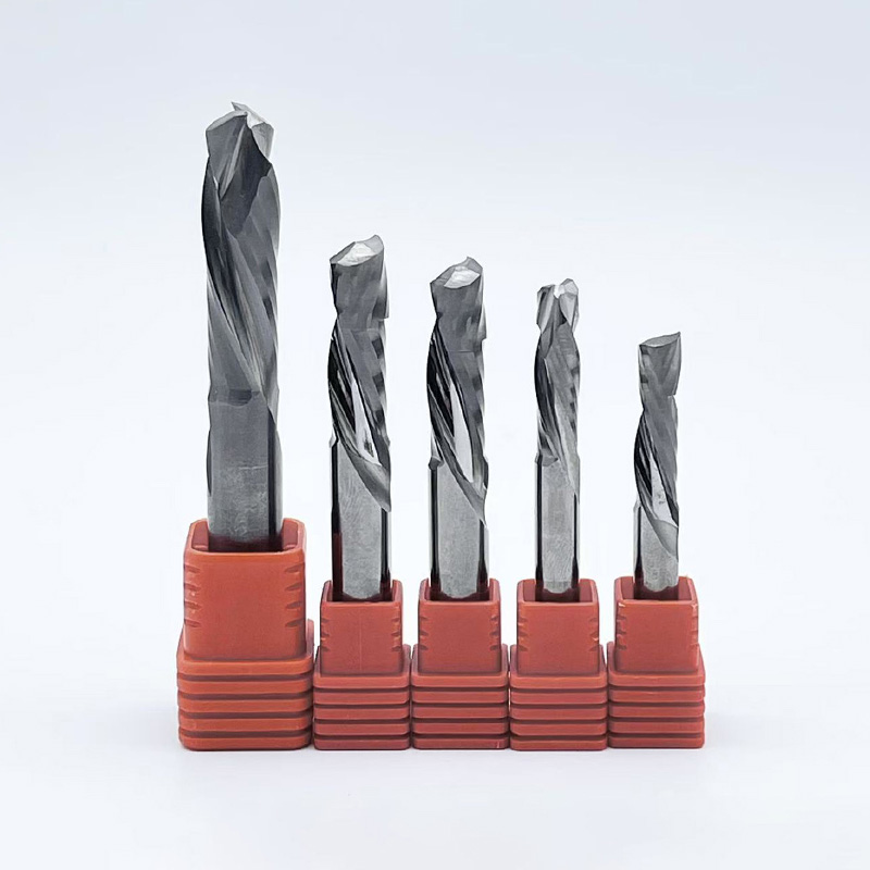
A compression bit is a single cutting tool featuring two distinct spiral directions on its cutting edge. The lower portion of the bit features an up-cut geometry, characterized by a right-hand spiral. Meanwhile, the upper portion of the bit features a down-cut geometry, characterized by a left-hand spiral.
The precise point where these two opposing spirals meet is known as the transition line. Grinding this complex geometry requires state-of-the-art CNC machinery. This precision manufacturing makes these tools highly specialized for panel processing.
The effectiveness of compression end mills relies on fundamental physics. As the tool rotates through the material, the up-cut tip pulls the wood fibers upward. This prevents the bottom veneer from splintering. Simultaneously, the down-cut upper section pushes the wood fibers downward. This prevents the top veneer from lifting.
These opposing forces collide exactly at the transition line. All shearing pressure is directed toward the dense core of the material. This squeeze effect essentially compresses the core fibers. Both the fragile top and bottom outer layers remain completely undisturbed.
Understanding the directional forces of different router bits is critical for optimizing your cut quality. Below is an objective technical comparison of the three primary tool geometries used in panel processing.
Tool Geometry | Top Edge Quality | Bottom Edge Quality | Chip Evacuation | Best Application |
|---|---|---|---|---|
Up-Cut | Poor — Severe Tear-out | Excellent | Excellent — Pulled Upward | Fast, deep cuts in solid materials |
Down-Cut | Excellent | Poor — Blow-out | Poor — Packed Downward | Shallow dadoes, sizing, pocketing |
Compression | Excellent | Excellent | Moderate — Directed to Core | Through-cuts on double-sided laminates |
Up-cut bits feature a right-hand spiral acting like an auger. They pull material upward and out of the cut channel. This provides superior chip evacuation, prevents heat buildup, and extends tool life. Unfortunately, the upward pulling force will almost certainly cause severe tear-out on the top face of veneered plywood.
Down-cut bits feature a left-hand spiral pushing material downward. The downward pressure cleanly shears the top veneer, leaving a pristine upper edge. However, they cause tear-out on the bottom edge. More importantly, they pack chips downward into the cut path. In dense materials like MDF, this trapped dust causes severe friction. Friction leads to burning and premature tool failure.
For through-cuts on double-sided materials, selecting proper plywood cutting tools utilizing compression geometry is the superior choice. By combining the benefits of both up-cut and down-cut profiles, they neutralize the shearing forces on both outer faces. When programmed correctly, they yield a clean, finished edge on both sides of the panel. This completely eliminates the need for secondary sanding operations.
Not all tools are manufactured to the same specifications. When sourcing woodworking CNC tools for industrial environments, material composition and specific design parameters directly impact performance.
Choosing between standard and mortise designs depends entirely on your programmed cut depth. Standard compression bits feature a longer up-cut section at the tip. This often ranges from 0.250 to 0.375 inches on a half-inch bit. They are engineered purely for full-depth profile cutting where the tool passes entirely through the material.
In contrast, mortise compression bits feature a much shorter up-cut section, typically around 0.125 to 0.200 inches. They are designed for shallow operations like cutting dadoes, grooves, or mortises. Because the up-cut section is short, the down-cut geometry engages the top veneer almost immediately. This prevents tear-out even on shallow passes.
For cutting engineered woods, solid carbide is an absolute requirement. High-Speed Steel is far too soft to withstand the highly abrasive nature of plywood glues and MDF resins. An HSS bit will lose its edge within minutes of cutting MDF.
Premium compression tools are manufactured from micro-grain solid tungsten carbide. The micro-grain structure provides a denser, more uniform cutting edge. It balances hardness for wear resistance with toughness to prevent micro-fracturing. Advanced tool coatings like DLC or TiSiN provide a hardened, low-friction barrier. This reduces heat accumulation and prevents synthetic resins from adhering to the cutting edge—a destructive phenomenon known as galling.
The number of flutes on a tool dictates the feed rate and the finish quality. Single-flute tools provide maximum space for chip evacuation. They are ideal for smaller, less rigid CNC machines that cannot push the tool at high speeds. Two-flute bits are the industry standard for most woodworking applications. They offer an optimal balance between cut speed, chip clearance, and edge finish. Three-flute tools are reserved for heavy, highly rigid industrial CNC machines requiring significantly faster feed rates.
Even the highest quality compression bit will cause tear-out if it is not utilized correctly. Proper CNC programming and toolpath strategy are essential for maximizing the tool's effectiveness.
The most critical rule of using a compression bit is ensuring the initial cut depth passes the transition line.
If your first pass is too shallow, only the up-cut portion of the bit will engage the material. This acts exactly like a standard up-cut bit, pulling the top veneer up and causing severe tear-out. To achieve true chip free cutting, the first pass must plunge deep enough so that the down-cut portion of the flute engages the top surface of the material. This pushes the veneer downward securely.
Never plunge a compression bit straight vertically down into the material. The bottom of the bit pushes chips upward while the top pushes chips downward. A direct Z-axis plunge traps all the material in the center of the bit. This causes extreme heat, burning, and can easily snap the tool.
Instead, always program a ramp or lead-in toolpath. Ramping moves the tool diagonally into the material, typically at a 3-degree to 5-degree angle. This allows the bit to clear chips horizontally as it descends to its target depth.
When cutting small parts from a large sheet of plywood or MDF, vacuum hold-down systems struggle to keep the pieces stationary once they are completely severed. If a part shifts mid-cut, it will ruin the edge and potentially shatter the tool.
To counter this, onion skinning is a proven CNC strategy. The machine is programmed to cut through the material but leave a microscopic layer—the onion skin, usually 0.020 to 0.030 inches thick—at the bottom of the board. This keeps the vacuum seal intact and the parts locked in place. A final rapid pass removes the remaining skin to free the parts cleanly.
Tool life and cut quality are dictated by the relationship between spindle speed and machine movement speed. Balancing these two metrics creates the proper chip load.
In CNC machining, the goal is to transfer the heat generated by friction into the wood chip. That chip is then ejected from the cut. If the tool spins too fast while moving too slowly through the material, it produces fine dust instead of chips.
Dust cannot absorb heat. Consequently, the heat transfers directly into the solid carbide tool. Excessive heat breaks down the cobalt binder in the carbide. This dulls the tool prematurely and causes the resin in MDF or plywood to burn, leaving dark scorch marks on the material edges. Proper optimization requires aggressive enough feed rates to produce distinct chips.
Calculating the correct chip load requires referencing the tool manufacturer's specifications. However, for a standard 1/2-inch, 2-flute compression bit cutting 3/4-inch plywood or MDF, consider this baseline starting parameter:
Spindle Speed: 16,000 to 18,000 RPM
Feed Rate XY Axis: 400 to 600 Inches Per Minute
Plunge Rate Z Axis: 100 to 150 IPM utilizing a ramp
Target Chip Load: 0.015 to 0.025 inches per tooth
Keep in mind, these parameters must be adjusted based on the rigidity of your specific CNC router and the effectiveness of your vacuum hold-down system.
Plywood and MDF are notoriously challenging materials to machine due to their abrasive glues and fragile veneers. However, severe edge chipping is completely preventable.
Specialized compression end mills solve this mechanical problem by pushing wood fibers inward during the cut, neutralizing the forces that cause tear-out. Upgrading your equipment to include these highly engineered bits eliminates wasted material costs and significantly reduces your sanding time.
By prioritizing technical specifications over initial purchase price, shops can drastically reduce their cost-per-cut and minimize machine downtime. Ready to elevate your fabrication quality? Evaluate your current cut parameters, select the right transition line for your material thickness, and invest in premium solid carbide tooling today. Find the exact specifications your shop needs at SS End Mill to guarantee flawless, pristine finishes on every single project.
From a safety and mechanical standpoint, using compression bits in a manual hand-held router is strongly discouraged. Compression geometry is engineered specifically for rigid machinery. The design inherently creates opposing axial forces. In a rigid CNC spindle, these forces cancel each other out. However, in human hands, these opposing forces cause unpredictable, violent chatter. The router will actively fight your control, posing a severe safety hazard. For hand-held routing on veneered materials, it is safer to use a standard down-cut bit for shallow passes.
If you are experiencing top-edge tear-out despite using high-quality tools, the issue almost universally stems from an incorrect depth on your first pass. Every compression bit features a transition line. For the downward-shearing action to protect the top veneer, the top surface of the material must sit completely above this transition line during the cut. If your first pass is too shallow, the down-cut flutes will never engage the material. The bit will act purely as an up-cut tool, lifting and splintering the top veneer.
Tool lifespan is entirely dependent on the abrasiveness of the material, the rigidity of your machine, and your specific feeds and speeds. The primary cause of premature tool wear is heat. Heat breaks down the cobalt binder in the solid carbide. Heat is generated by friction when a tool is spinning too fast but moving through the material too slowly. By maintaining a proper chip load, heat is transferred into the wood chips rather than the tool itself. Under optimized parameters, premium bits can process dozens of sheets of abrasive plywood before requiring replacement.
While both materials benefit heavily from compression geometry, their distinct physical properties dictate slight variations in optimal tool selection. Plywood requires a tool with a very sharp cutting edge and high shear angles to cleanly slice the fibers. Conversely, MDF is a dense composite with no grain direction, prone to generating fine dust and heat buildup. While specialized MDF bits exist with lower rake angles to improve durability, a high-quality 2-flute solid carbide compression bit is highly versatile. It will deliver exceptional, tear-free edges on both materials if proper feed rates are maintained.
Cutting small parts from double-sided laminates presents a unique challenge. Because a compression bit's up-cut portion lifts the bottom of the material, it can easily overcome the vacuum hold-down suction on small surface areas. To solve this, operators should utilize the onion skinning technique. This involves programming the CNC to cut through the material, leaving only a paper-thin layer of wood at the bottom of the board to maintain the vacuum seal. A final full-depth pass is then executed to remove the remaining skin cleanly without dislodging the workpiece.
Optimal parameters depend heavily on tool diameter and flute count. Generally, a 1/2-inch two-flute compression bit performs best between 16,000 and 18,000 RPM with a feed rate of 400 to 600 IPM. The critical metric is chip load, which should typically range from 0.015 to 0.025 inches per tooth. If your machine lacks the rigidity to push 500 IPM, you must lower your RPM proportionally to prevent the tool from burning the material.
Yes, solid carbide compression bits can be professionally sharpened. However, sharpening reduces the overall cutting diameter of the tool. You must update your CNC software's tool library with the new diameter to maintain dimensional accuracy on your cut parts. Additionally, the complex geometry of the transition line requires specialized CNC grinding equipment to sharpen correctly without ruining the up-cut to down-cut ratio.