Please Choose Your Language
- All
- Product Name
- Product Keyword
- Product Model
- Product Summary
- Product Description
- Multi Field Search

Views: 0 Author: Site Editor Publish Time: 2026-09-19 Origin: Site

Snapping an expensive micro end mill mid-cut is a machinist's worst nightmare. Hearing that dreaded high-pitched squeal before a sudden snap usually means your fragile cutter just deflected into a hardened steel wall. Reaching into deep pockets, steep walls, or tiny cavities inherently requires instruments with extended length. As the reach of a cutter increases, its structural rigidity decreases exponentially. This leads to severe deflection, harmonic chatter, and ultimately, poor dimensional accuracy.
Balancing reach and rigidity separates average job shops from elite precision manufacturers. You must understand tool geometry and the physics of cutting forces. A flawless machine setup is absolutely non-negotiable. A top-tier cutter will still fail instantly if the spindle lacks concentricity. In this guide, we explore how to select and optimize tooling strategies to efficiently tackle deep geometries without destroying your tooling budget or sacrificing part precision.
The Length to Diameter Ratio is Critical: The extension ratio fundamentally dictates rigidity. A 3 to 1 ratio is standard. Exceeding a 5 to 1 ratio requires specialized geometries. Anything beyond 10 to 1 demands highly optimized cutting strategies.
Reach vs Flute Length: Using cutters with short, stubby flutes and relieved necks drastically improves stability in deep cavities compared to traditional long-flute designs.
Deflection Kills Accuracy: Even microscopic bending pushes the cutter away from the workpiece. This phenomenon causes dimensional inaccuracies, tapered walls, and unacceptable surface finishes.
Setup Matters as Much as the Tool: Premium holders and near-zero spindle runout are mandatory. Total indicated runout must remain strictly under 3 microns.
Milling miniature parts with high dimensional accuracy is inherently difficult in the realm of precision manufacturing. When those components feature steep walls or blind pockets, the operational complexity multiplies. Shop floor engineers must constantly balance the necessity of reaching the bottom of a feature with the physical limitations of fragile carbide.
Operations utilizing cutters with diameters under 3.0mm generally fall into the micro category. In this microscopic environment, the concept of depth is relative. We measure this using the Length-to-Diameter ratio. This metric compares the overall extended reach to the actual cutting diameter.
Consider these benchmarks to truly grasp the operational difficulty. Up to a 3 to 1 ratio is considered standard. This allows for conventional feeds and speeds. Moving into the 3 to 1 up to 5 to 1 range introduces moderate difficulty. You must use necked shanks and reduce your chip load. Pushing into the 5 to 1 up to 10 to 1 territory is highly challenging. This mandates tapered neck designs and strict runout control. Extreme applications between 10 to 1 and 20 to 1 demand specialized techniques, advanced CAM strategies, and premium shrink-fit holders. Programming a 1mm piece of carbide to extend 10mm out of the holder without bending under lateral force pushes the absolute boundaries of material science.
The demand for complex internal geometries spans several high-tech industries. Medical device manufacturing frequently requires pristine surface finishes on titanium bone plates and micro-fluidic channels to prevent bacterial adherence. The aerospace sector relies heavily on sensors and micro-valves carved from notoriously tough high-temperature alloys like Inconel. Injection mold makers often need to carve deep, narrow ribs directly into hardened tool steel up to HRC 65. Their goal is to avoid costly and time-consuming Electrical Discharge Machining processes.
You must understand the mechanical conflict between extension and stiffness to successfully navigate deep features. As a shank gets longer to accommodate a deep pocket, its structural integrity decreases at an alarming rate.
Deflection is the physical bending of a solid object when subjected to radial cutting forces. In practice, you can model a small diameter cutter as a cantilever beam fixed at the collet and subjected to a load at the cutting edge.
The physical formula for cantilever beam deflection dictates that bending increases to the cube of the length. It simultaneously decreases to the fourth power of the diameter. Specifically, doubling the length to reach a deep cavity makes the tool eight times more susceptible to bending. Reducing the diameter by half makes it sixteen times weaker. Combining a tiny diameter with a long reach creates a scenario where the risk of catastrophic failure skyrockets.
A fragile end mill bends away from the workpiece instead of shearing the material cleanly when it deflects. This microscopic yielding leads to severe manufacturing defects. The cutter pushes away from the cut and leaves excess material on the walls. This results in a pocket that is wider at the top and narrower at the bottom. We call this defect tapering. This bouncing effect also acts like a tuning fork. It creates harmonic vibrations that destroy the surface finish and cause micro-impacts on the fragile carbide edges. Premature chipping is inevitable.
Selecting the correct macro-geometry is the most critical bottom-of-funnel decision a manufacturing engineer makes. Not all extended-length instruments are created equal. Choosing the wrong one guarantees scrap parts.
A remarkably common mistake on the shop floor is utilizing an end mill with a long flute length for deep pockets. They can technically reach the bottom. However, the flutes remove vital mass from the core and make the structure incredibly weak. Long flutes also increase the surface area in contact with the workpiece. This generates excessive friction and lateral pressure.
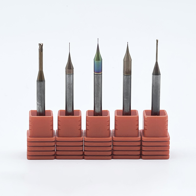
Relieved neck designs are the correct choice. These long reach end mills feature a very short cutting length designed strictly for the required depth of cut per pass. Behind the flutes, the shank steps down to a diameter slightly smaller than the cutting diameter. This non-cutting neck provides necessary clearance without rubbing against cavity walls. It maintains a solid carbide core for maximum stiffness.
To make selection easier for your specific application, review this structural comparison based on standard micro tooling profiles.
Tool Geometry | Core Rigidity | Max L to D Ratio | Best Application Scenario |
|---|---|---|---|
Long Flute | Very Low | Up to 3 to 1 | Peripheral finishing on shallow, open walls. High risk of chatter. |
Straight Relieved Neck | Medium | Up to 10 to 1 | Deep, perfectly straight vertical walls with zero draft angle clearance. |
Tapered Neck | Extremely High | 10 to 1 up to 20 to 1 | Deep mold cavities and ribbed features where a slight draft angle is permissible. |
Tapered neck tools are considered the gold standard for deep mold making. The neck diameter gradually increases as it moves away from the cutting edge toward the shank. This taper adds massive cross-sectional mass to the core. Utilizing a tapered neck significantly reduces deflection and allows for far more aggressive feed rates if your cavity geometry permits a draft angle.
The micro-geometry and metallurgical composition play a vital role in preventing breakage during high-stress operations. This goes far beyond the basic dimensions of extension and flute length.
Standard tungsten carbide is simply insufficient for microscopic applications. Because micro milling tools possess such minuscule cross-sectional areas, they require materials with exceptionally high Transverse Rupture Strength to resist snapping under heavy chip loads.
High-performance options are manufactured from ultra-fine or sub-micron grain carbide. Premium micro tools typically feature grain sizes around 0.2 microns. These smaller grains allow for a higher density of carbide particles packed tightly together with an optimized cobalt binder. This dense metallurgical structure prevents micro-cracks from propagating through the core. It keeps the delicate cutting edges intact even when engaging hardened tool steels.
The core diameter is the solid center portion measured between the depths of the flutes. A thicker core directly equates to a stronger foundation. Two-flute designs offer larger valleys for excellent chip evacuation. They are ideal for gummy materials like aluminum where chip packing is a major risk. Four-flute tools provide a much thicker core diameter to maximize rigidity. They are the preferred choice for harder materials like stainless steel or titanium.
Friction is the ultimate enemy in deep cavities. Chips and heat have nowhere to escape. Advanced physical vapor deposition coatings indirectly reduce deflection by lowering the coefficient of friction. They also protect the carbide substrate from thermal shock. Coatings like TiSiN or specialized nanocomposite layers are excellent for high-temperature alloys and hardened steels up to HRC 65. They maintain razor-sharp edges over long production runs.
Investing thousands of dollars in premium cutters is completely futile if the machine environment introduces instability. Deep feature accuracy is a system-wide engineering challenge that starts directly at the spindle.
Runout is the degree to which a cutter rotates off its true theoretical axis. A runout of 12 microns might cause slight premature wear in macro-scale manufacturing. It is absolutely catastrophic in the micro realm.
The chip load becomes wildly uneven if you are spinning a 0.25mm end mill and your spindle has just 2.5 microns of runout. One flute takes a massive bite of material while the opposite flute cuts nothing. This asymmetrical force violently pushes the instrument off-center. It causes immediate deflection and instantaneous breakage. Total indicated runout at the tool tip must be kept strictly under 3 microns.
Standard ER collet chucks are generally not accurate or rigid enough for high extension applications. Machinists must utilize precision CNC tools for workholding to achieve near-zero runout. Shrink fit holders utilize thermal expansion to grip the shank across its entire circumference. This offers the lowest possible runout and a slim profile to avoid collisions. Hydraulic chucks use pressurized fluid to compress an internal membrane. They provide excellent concentricity and superior vibration damping to mitigate chatter.
The toolpath is the final piece of the manufacturing puzzle. How you program the machine dictates the exact forces applied to the delicate carbide.
Radial cutting forces must be minimized to control bending. You achieve this by drastically reducing the step-over. Taking lighter lateral passes reduces the pressure on the cantilevered tool. This keeps it straight and true. The axial step-down can often be maintained if the step-over is kept extremely light. We typically recommend between 5 percent and 10 percent of the overall cutter diameter.
High-Efficiency Machining is a modern deep cavity machining strategy. It utilizes a small radial step-over combined with high feed rates and spindle speeds. The toolpath moves in circular, trochoidal motions rather than aggressive straight lines. This ensures a constant engagement angle. It prevents the cutter from burying itself in sharp corners. Spiking cutting forces cause instant failure. HEM maintains a steady, low-pressure load for safe and highly accurate roughing.
You should never plunge a miniature end mill straight down into solid material. They have very little center-cutting clearance. Plunging creates massive axial pressure that will crush the core. Programmers must use a helical entry to spiral down into the material. A very shallow ramp angle of 1 to 2 degrees is also acceptable. This allows the side flutes to gradually clear material and safely establish the initial pocket depth.
The global push toward extreme miniaturization is forcing rapid evolution in manufacturing equipment. Medical implants and aerospace micro-valves demand increasingly tighter tolerances inside deeper internal geometries. We are witnessing a massive transition away from traditional EDM processes toward direct hard milling.
This shift requires cutters equipped with hyper-engineered neck transitions and advanced nanocomposite coatings to survive extreme thermal loads. Tool manufacturers are responding by developing ultra-rigid tapered geometries from proprietary 0.2-micron carbide blends. The integration of predictive CAM software is also revolutionizing shop floor workflows. Modern software simulates cutting forces in real-time. It automatically adjusts feed rates to prevent tool deflection before the spindle even powers on. This synergy between metallurgical science, precise workholding, and intelligent toolpaths makes direct hard milling of deep cavities a reliable daily reality.
Successfully navigating deep features requires a holistic approach. You must blend the right geometry with flawless execution. Follow this practical checklist to ensure success on your next project.
Calculate the Extension Ratio: Determine exactly how far the cutter needs to extend beyond the holder to clear the deepest pocket.
Minimize Flute Length: Choose the shortest possible cutting length to maximize core strength. Never use a long-flute tool if a stub-flute necked tool will work.
Optimize the Neck Profile: Opt for a tapered neck if the part geometry allows a draft angle. Use a straight relieved neck for perfectly vertical walls.
Match the Coating: Select a TiSiN or nACo coating for hardened steels up to HRC 65 to reduce friction and thermal shock.
It is time to upgrade your setup if you are struggling with accuracy, tapering, or frequent breakage on deep features. Precision is a deliberate choice that starts with selecting the right instrument for the job.
Mastering deep features in miniature components requires a profound understanding of the delicate balance between reach and rigidity. Every millimeter of extended length exponentially increases the risk of deflection, chatter, and catastrophic failure. Machinists can conquer even the most demanding extension ratios by leveraging relieved neck geometries, sub-micron grain carbide, near-zero runout tool holders, and advanced HEM toolpaths.
Investing in high-quality, application-specific tooling directly impacts your bottom line. It reduces scrap rates, eliminates the need for secondary EDM processes, and prevents the costly downtime associated with digging broken carbide out of expensive parts. Explore our extensive range of engineered solutions at SS End Mill to find the exact high-rigidity, long-reach micro tools your production demands.
A 3 to 1 ratio is considered standard for conventional milling. Specialized extended reach end mills can achieve 10 to 1 or even 20 to 1 ratios in specific applications. Anything over 5 to 1 requires highly specialized CAM programming, ultra-low runout holders, and significantly reduced radial depths of cut to prevent snapping.
The most common causes of premature breakage are poor chip evacuation, excessive spindle runout, or using a design with a flute length that is too long. The cutter will attempt to re-cut chips if they are not blasted out of the deep pocket. This causes an instant spike in lateral force that crushes the fragile carbide core.
Flute length refers strictly to the fluted, cutting portion of the tool. Reach includes both the flutes and the relieved, non-cutting neck behind them. You always want the shortest flute length possible combined with a relieved neck for deep cavities. This maximizes the solid carbide mass and overall rigidity.
An end mill bends away from the programmed CNC toolpath when it deflects under load. The cutter is no longer perfectly straight, so it leaves excess material on the walls of your part. This results in tapered walls where the top of the pocket is wider than the bottom. It completely throws off strict geometric tolerances.
Standard flood coolant often fails to reach the bottom of deep micro cavities. You must use high-pressure through-spindle air blasts or specialized Minimum Quantity Lubrication systems. These methods continuously evacuate chips upward and out of the cutting zone before the tool can re-cut them.
Standard ER collet chucks are not recommended for micro milling, especially in deep reach applications. They inherently possess too much runout. You should upgrade to shrink-fit holders or high-precision hydraulic chucks to guarantee the total indicated runout remains under 3 microns at the tool tip.