Please Choose Your Language
- All
- Product Name
- Product Keyword
- Product Model
- Product Summary
- Product Description
- Multi Field Search

Views: 0 Author: Site Editor Publish Time: 2026-09-22 Origin: Site

Picture a CNC router plunging into a high-value carbon fiber aerospace panel. The spindle hums, the final pass begins, and then a distinct cracking sound echoes through the shop. The top layer splinters entirely. A single machining error can instantly ruin expensive composite components. Delamination remains the leading culprit behind massive scrap rates in carbon fiber manufacturing. In this comprehensive guide, we will explore how specific nonmetal tooling geometries neutralize cutting forces to prevent this costly issue directly at the source.
Delamination is preventable: Understanding the mechanical differences between peel-up and push-out delamination is the critical first step to stopping layer separation.
Tool geometry is everything: Specialized engineering designs are explicitly manufactured to compress composite layers together rather than pulling them apart.
Material matters: Carbon and glass fibers are notoriously abrasive. Upgrading to advanced carbide or diamond-coated solutions is an absolute requirement for maintaining edge sharpness.
Proper parameters: Pairing the correct cutting geometries with optimized spindle speeds and feed rates prevents friction-induced heat buildup, thereby avoiding resin degradation.
To effectively machine composite materials, you must first understand their physical architecture. Carbon Fiber Reinforced Polymers and fiberglass are anisotropic. This means their mechanical properties shift dramatically depending on the orientation and direction of the fibers. Unlike a homogeneous block of aluminum, composites consist of highly abrasive, high-tensile-strength strands suspended in a relatively soft, brittle resin matrix, which is usually epoxy.
When a cutting edge interacts with this dual-phase material, the varying resistance between the hard structural fibers and the soft binding matrix creates chaotic cutting dynamics. If the applied forces exceed the interlaminar bond strength of the resin, the layers inevitably separate. This separation immediately compromises the structural integrity and load-bearing capacity of the component.
Peel-up delamination occurs at the top surface of the composite workpiece. As a rotating tool enters the material, traditional helical flutes generate an upward axial pull. If the edge is not dead-sharp, or if the helix angle is excessively aggressive, this lifting force overpowers the adhesive strength of the epoxy matrix. Consequently, the top layers of fibers are peeled away from the underlying structure before they can be cleanly sheared. This leaves a frayed and rejected edge.
Conversely, push-out delamination happens at the bottom surface of the workpiece upon tool exit. As the cutter pushes downward through the final layers of the composite, the remaining uncut material becomes extremely thin and loses its structural stiffness. The downward thrust force bends and pushes these unsupported bottom fibers outward. This fractures the resin matrix and causes severe splintering on the back of the panel.
Mechanical stress is not the sole cause of layer separation. Thermal dynamics play a major and often overlooked role. The epoxy resins used in composite panels have a relatively low glass transition temperature, typically hovering between 150 and 200 degrees Celsius. If a dull tool rubs against the abrasive fibers instead of slicing them, the resulting friction generates intense localized heat. This thermal spike melts or smears the resin matrix. Weakening the bond between layers severely exacerbates both peel-up and push-out delamination.
Delamination Type | Location | Primary Cause | Force Direction |
|---|---|---|---|
Peel-Up | Top Surface | High upward axial force, dull cutting edges | Upward Lifting |
Push-Out | Bottom Surface | High downward thrust force, lack of bottom support | Downward Bending |
Thermal | Entire Cut Zone | Friction from worn tools, incorrect feed or speed | Multidirectional |
Engineers and machinists accustomed to working with steel or titanium often attempt to use standard High-Speed Steel or conventional end mills on composite panels. This approach almost universally results in high scrap rates, poor surface finishes, and rapid tool failure. Standard metal-cutting instruments are structurally and geometrically unsuited for composites for two primary reasons. These include the sheer abrasiveness of the material and the fundamental mechanics of the cut.
Carbon and glass fibers possess extremely high tensile strength and hardness. On a microscopic level, cutting through these strands is akin to machining a solid block of sandpaper. Standard High-Speed Steel tools lack the required hardness to withstand this abrasion and will lose their cutting edge within minutes. Even standard micro-grain carbide designed for metal will suffer from rapid flank wear when exposed to continuous fiber abrasion. Operators often notice that when a tool loses its edge, the spindle load spikes slightly. This is a clear warning sign that the tool has stopped severing the fibers and begun to plow through them.
Standard metal tools are engineered to shear homogeneous materials. They rely on specific rake angles and large flute valleys to shear off continuous metal chips that evacuate heat away from the cutting zone. Composites, however, do not behave this way. Because of their brittle matrix, carbon and fiberglass fracture and shatter at the point of contact, turning into fine, highly abrasive dust.
Metal-cutting designs with high helix angles are entirely inefficient at managing this dust. Furthermore, the aggressive lifting action directly contributes to peel-up delamination. To achieve clean cuts and maintain strict quality control, manufacturing facilities must transition to specialized nonmetal solutions. These specialized instruments are not an optional luxury. They are a mandatory engineering requirement for producing defect-free components.
Looking at the broader manufacturing landscape, the shift toward lightweighting in aerospace and electric vehicle sectors has triggered an unprecedented surge in composite component volume. However, recent industry data highlights a severe bottleneck. Machining-induced delamination accounts for a staggering percentage of total scrap costs. The prevailing trend shows top-tier facilities aggressively abandoning repurposed metalworking tools. Instead, the industry is standardizing on dedicated nonmetal machining solutions to achieve zero-defect tolerances. This shift is essential for supporting highly automated production environments where manual rework is no longer financially viable.
Eliminating delamination requires geometries that actively neutralize axial forces and cleanly sever tough fibers. Tooling manufacturers have developed several specific designs to address the unique challenges of modern composites.
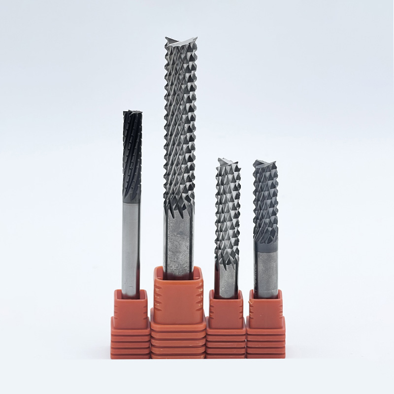
One of the most effective solutions for routing and slotting composite panels is the micro toothed end mill, commonly referred to in the shop as a corn cob router or diamond-cut router. Instead of having two or four continuous helical flutes, this design features dozens of small, interlocking cutting teeth distributed along the cutting length. High-performance models often feature ultra-dense tooth configurations to maximize fiber shearing.
This geometry excels because the numerous teeth engage the material in tiny increments. Instead of pulling on long, continuous strands of carbon fiber, the micro-teeth grind and fracture the fibers into microscopic dust particles. The intersecting up-cut and down-cut angles of the individual teeth cancel out the overall lifting and pushing forces. This keeps the composite layers perfectly intact. Additionally, the interrupted cutting action allows for better airflow and heat dissipation, preventing the resin matrix from reaching its melting point.
When edge trimming or profiling panels, maintaining a pristine top and bottom edge is critical. The compression router is widely regarded as the premier CFRP milling cutter for this specific application. It features a unique dual-helix design. The lower portion of the cutting length has an up-cut geometry, while the upper portion has a down-cut geometry.
As the tool engages the material, the up-cut flutes pull the bottom layers upward, and the down-cut flutes push the top layers downward. This creates a highly effective compression zone at the center of the workpiece. By forcing all the composite layers inward toward the core, the compression router completely neutralizes both peel-up and push-out forces simultaneously. The result is a perfectly clean, delamination-free edge.
While carbon and glass share similar machining challenges, glass fibers exhibit slightly different mechanical behaviors. They are incredibly tough and tend to bend or flex before they shear. If a tool is not perfectly optimized, it will leave a fuzzy edge where the glass strands were torn rather than cut cleanly.
A dedicated fiberglass cutter is engineered with an ultra-sharp cutting edge and specific rake angles designed to slice through the tough strands with minimal deflection. These often feature a higher number of flutes to ensure a higher frequency of cuts per revolution. This severs the glass fibers before they have a chance to bend away from the cutting zone.
Even the most perfectly designed geometry will fail if the underlying substrate material cannot withstand the harsh environment of composite machining. The selection of tool material directly dictates the lifespan, edge retention, and ability to prevent layer separation over long production runs.
For the vast majority of nonmetal applications, carbide composite tools serve as the industry baseline. Machining carbon fiber requires solid sub-micrograin or ultra-fine grain tungsten carbide, where the particles are typically smaller than 0.4 to 0.8 microns. This ultra-fine structure provides a superior combination of hardness and transverse rupture strength. The dense grain structure allows manufacturers to grind an aggressively sharp edge without it crumbling or micro-chipping. A razor-sharp edge is an absolute necessity for slicing through fibers.
In high-volume aerospace or automotive production environments, the extreme abrasiveness of carbon fiber will wear down even the best uncoated carbide too quickly. In these scenarios, upgrading to diamond technology becomes an economic necessity.
Chemical Vapor Deposition grows a layer of real crystalline diamond directly onto the carbide substrate. This maintains complex geometries while increasing surface hardness to nearly 10,000 Vickers Hardness. This drastically reduces abrasive wear and extends tool life by up to fifteen times. Alternatively, Polycrystalline Diamond tools feature diamond wafers brazed onto a carbide body. While limited to simpler profiles, they offer the ultimate wear resistance, often outlasting standard carbide by fifty times or more.
Beyond the overarching tool type, the specific micro-geometries ground into the composite cutting tools dictate their success in preventing delamination. Attention to flute count, helix angles, and edge preparation is paramount.
When machining metals, low flute counts provide large valleys for chip evacuation. Because composites produce fine dust, large flute valleys are unnecessary. Instead, nonmetal tools often feature higher flute counts such as four, six, or eight. This increases the core diameter for maximum rigidity. It also increases the number of cutting edges engaging the material per revolution, ensuring fibers are sheared rapidly and cleanly.
The helix angle directly influences the direction of cutting forces. Traditional high-helix end mills generate massive axial forces, which act as the primary cause of peel-up delamination. Tools designed for carbon fiber typically utilize very low helix angles between five and fifteen degrees. Some even use straight flutes at zero degrees to direct forces radially into the side of the cut, keeping the composite layers intact.
In metalworking, cutting edges are often honed or given a microscopic radius to prevent chipping. When machining carbon fiber and fiberglass, honing is strictly prohibited. The tool must possess a dead-sharp edge. Any radius will cause the tool to push and rub against the fibers rather than slicing them. This instantly generates heat and leads directly to delamination.
Applying the right tool with the wrong parameters will still scrap the part. Unlike isotropic metals that plastically deform, composite materials are anisotropic and brittle. Achieving a perfect cut requires a precise balance of spindle speed, feed rate, and thermal management.
The fundamental principle of composite machining is maintaining high spindle speeds coupled with relatively low feed rates. High cutting velocities are critical because carbon and glass fibers possess immense tensile strength. If the edge strikes the fiber too slowly, the fiber has time to bend or deflect. By utilizing high spindle speeds, the cutting edge impacts the fiber with enough kinetic energy to snap it cleanly.
Feed rates must be carefully controlled. If the feed is too aggressive, the tool engages too much material, forcing the layers apart and causing push-out delamination. However, the feed cannot be so low that the tool merely rubs against the material. Rubbing generates excessive friction and catastrophic thermal damage.
Heat is the silent destroyer of composites. While metal machining relies heavily on flood coolant, liquid coolants are generally avoided in this sector. Composites can absorb moisture, which degrades their mechanical properties. Furthermore, when coolant mixes with fine composite dust, it creates a highly abrasive slurry that prematurely wears out machine guideways and spindle seals.
Therefore, dry machining is the industry standard. Machinists rely on optimized tool geometries to minimize friction and employ high-velocity vacuum dust extraction systems. These powerful local vacuums remove hazardous dust while pulling ambient air across the cutting zone, providing necessary convective cooling.
The direction of the tool path significantly impacts edge quality. In conventional milling, the cutting edge enters at zero thickness and exits at maximum thickness, pulling the material upward. Climb milling is almost universally recommended for profiling composites. In climb milling, the tool enters at maximum thickness and pushes down and inward against the uncut substrate. This acts as a rigid backing to support the fibers as they are sheared.
Material Type | Tool Material | Surface Speed Feet per Minute | Feed per Tooth Inches | Milling Strategy |
|---|---|---|---|---|
Standard Carbon Fiber | Solid Carbide | 400 to 800 | 0.001 to 0.003 | Climb Milling |
High Temperature Carbon Fiber | Diamond Coated | 800 to 1,500 | 0.002 to 0.005 | Climb Milling |
Fiberglass G10 or FR4 | Solid Carbide | 300 to 600 | 0.001 to 0.004 | Climb Milling |
For procurement managers, manufacturing engineers, and CNC machinists, selecting the correct tooling is a critical financial decision. The high upfront cost of composite panels means scrap rates must be kept near zero. Standard metal tools are a false economy. They might cost less initially but will inevitably cost exponentially more in ruined parts and machine downtime. To systematically select the right nonmetal machining solutions, evaluate your requirements across three main criteria.
Not all composites behave the same way under a spindle. Pure carbon fiber requires tools with extreme hardness and razor-sharp edges, making micro-toothed end mills highly effective for roughing. Fiberglass, being incredibly tough, demands dedicated cutters with specific rake angles to cleanly sever strands without leaving frayed edges. Honeycomb sandwich panels require specialized geometries that cut the tough outer skin without crushing the delicate core structure.
The geometry must perfectly match the physical operation. When finishing the outside dimensions of a panel, a compression cutter is optimal for neutralizing top and bottom delamination forces. For plunging or cutting internal features, a corn cob router excels at managing heat and preventing long fiber pull-out. Hole-making requires specialized composite drills with a unique point geometry to score the perimeter before the center web pushes through.
For low-volume production or research environments, uncoated sub-micrograin carbide offers the best return on investment. It provides the necessary sharpness without the high initial cost of diamond. In high-volume mass production, however, tool changes represent lost time, and dull edges risk scrapping expensive parts. Upgrading to diamond-coated tools or solid diamond inserts becomes an economic necessity. This extends tool life exponentially and results in a much lower cost-per-part over time.
Machining composites is a highly specialized discipline that leaves zero room for guesswork. Engineering teams should partner directly with manufacturers who specialize exclusively in nonmetal applications to leverage empirical data and custom recommendations tailored to specific matrixes.
Delamination frequently ruins extremely expensive composite parts, but it is a highly preventable manufacturing issue. By understanding the mechanics of layer separation and moving away from repurposed metalworking equipment, facilities can drastically improve their output quality. Always choose the correct geometry and substrate material for your specific application. Specialized nonmetal tools eliminate scrapped parts completely, ensuring this smart tooling investment pays for itself quickly. For engineers looking to eliminate scrap rates, selecting precision-engineered tools from a specialized manufacturer is the fastest path to zero-defect production. Browse the high-performance nonmetal machining solutions at SS End Mill to find the exact geometry and substrate for your specific composite matrix today.
The optimal choice depends directly on your specific machining operation. For edge routing and profiling external boundaries, a compression router is the best option. Its unique opposing flute design pushes the top and bottom layers of the carbon fiber inward, effectively neutralizing the axial forces that cause peel-up and push-out delamination. For internal slotting, pocketing, or roughing operations, a micro-toothed end mill is superior, as it grinds the material to prevent fiber pull-out.
Technically, a standard metal tool will cut fiberglass for a very brief period, but it is highly discouraged in professional manufacturing. Glass fibers are incredibly abrasive and will round off the cutting edge of standard High-Speed Steel or conventional carbide within minutes. Once the edge dulls, it stops shearing the fibers and begins to tear them. This results in severe heat buildup, matrix melting, heavy splintering, and ultimately, a ruined part. A dedicated fiberglass cutter with appropriate hardness and edge preparation is required to maintain part integrity.
Unlike standard end mills that feature two to four continuous flutes, a micro toothed end mill features dozens of small, overlapping cutting edges that resemble a corn cob. When machining composites, these numerous small teeth act more like a precision grinding wheel than a traditional shear cutter. They break the tough carbon or glass fibers into microscopic dust particles rather than grabbing and pulling on long, continuous strands. This grinding action minimizes the axial stress placed on the composite layers, keeping the laminated structure perfectly intact and leaving a clean, fray-free edge.
The primary difference lies in material hardness and abrasion resistance. Composite materials rely on fibers that are significantly harder and more abrasive than the chips produced by aluminum or steel. High-Speed Steel lacks the necessary wear resistance. The abrasive fibers act like sandpaper, destroying a steel edge almost instantly. Sub-micrograin carbide composite tools are engineered to be exponentially harder. This allows them to withstand the constant abrasion of the fibers while maintaining the razor-sharp edge required to sever the material without causing delamination.
Typically, high spindle speeds ranging from 10,000 to 20,000 RPM are recommended, depending on the tool diameter and specific matrix. High speeds ensure the fibers are impacted with enough kinetic energy to be sheared cleanly rather than bent or deflected away from the cutting edge.
Preventing fraying requires a dedicated cutter with a dead-sharp edge and a high flute count to maximize shear frequency. Additionally, using a climb milling strategy ensures the tool pushes the fibers against the uncut material, providing backing support that stops the tough glass strands from tearing.